arduino electronics Uncategorized usb windows
USB Monitor Buddy
I have two monitor speakers that each require turning on and off with switches at the back. Kind of annoying – I don’t like leaving them on all the time. So I decided I was going to make a simple box with two power receptacles and one switch, right in front of me so I don’t have to awkwardly reach around back of both of them. That should be pretty simple.
But then I had a thought that I was always having to switch between my wireless gaming headphones and my Steinberg audio interface via the Windows systray or control panel, and it would be nice to have a button on this box I was going to make to tell Windows to switch my default audio playback device.
So the plan formed: create a simple USB device with a button on it. A utility on my PC would respond to inputs from this USB device. A quick web search turned up this excellent tutorial for how to create a USB1.1 device: https://codeandlife.com/2012/01/22/avr-attiny-usb-tutorial-part-1/
On the device side, there’s the V-USB library that implements a USB firmware driver for Atmel’s AVR controllers – the MEGA238P sits at the heart of the Aduino Nano. I had a few sitting around, so I had a good starting point.
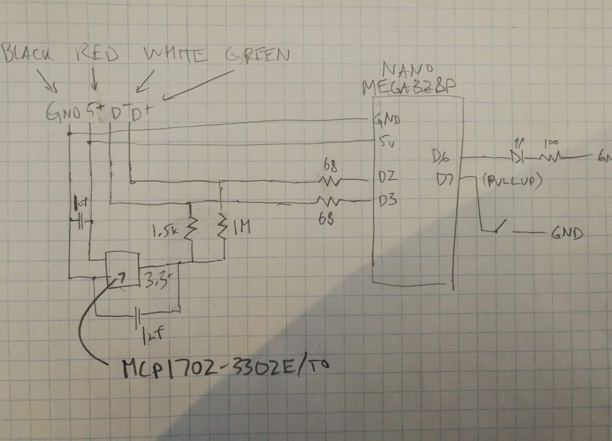
I selected a voltage regulator to pull the 5v that USB runs on down to 3.3v for the data lines. There’s a comment in that USB tutorial above that recommends choosing a regulator that draws minimal quiescent current (basically the overhead of the regulator alone) and an MCP1702-3302E-TO seemed to fit the bill. My schematic and breadboard look like this:

I use Visual Micro, but regardless of what your dev environment is, you basically just pull all the sources in v-usb into your project. If you’re using git, you can add it as a submodule:
git submodule add https://github.com/obdev/v-usb.git .
Next, edit the usbconfig.h file to your liking. If you’re building in Arduino IDE or Visual Micro, your .ino file will be compiled as C++ so you need to take some care given that V-USB is all C. Include headers via extern from your .ino or any .cpp files like so and any hooks you want V-USB to call back to belong in there too:
extern "C"
{
    #include "v-usb/usbdrv/usbdrv.h"

    void monitorBuddyBlinkLED()
    {
        if (blinkCallback)
        {
            blinkCallback();
        }
    }
}
If you don’t, usbPoll and usbInit will get C++ linkage in your cpp translation units and those symbols will be undefined when you link.
I found a few other sites to help familiarize myself with how USB worked and to help me visualize what I was trying to achieve:
- https://www.beyondlogic.org/usbnutshell/usb1.shtml
- https://www.keil.com/pack/doc/mw/USB/html/_u_s_b__endpoints.html
I concluded I really just needed one interrupt in endpoint to get button presses from the Arduino to the PC. In USB, the host (the computer the USB device is attached to) initiates all communication. So with something like a mouse, the computer is polling the device X times every second, and the device just publishes to a local buffer what the values should be. When the data is going from the device to the host, it’s called an in endpoint – as opposed to an out endpoint. The in/out terminology refers to the direction of the endpoint, and it’s relative to the host. Independent of the direction, there are four types of endpoints. Interrupt endpoints are for time sensitive data, so it’s appropriate for things that involve the user interfacing with the device. (Note: I may discover later I should be implementing this as a custom HID device as opposed to a custom/unknown class. This is all just for proof of concept.)
Anyhow, the meat of what’s happening on the Nano is as follows. To enable inturrupt endpoint 1 with v-usb, we set this in usbconfig.h:
#define USB_CFG_HAVE_INTRIN_ENDPOINT 1
In setup(), we init usb, trigger the host to re-enumerate devices, and set our starting endpoint data:
    usbInit();

    usbDeviceDisconnect(); // enforce re-enumeration
    delay(500);
    usbDeviceConnect();

    // enabled by default, I think
    // sei(); // Enable interrupts after re-enumeration
    // button
    pinMode(audioDeviceButton.pin, INPUT_PULLUP);
    usbSetInterrupt(&buttonState, 1);
In our loop(), we simply set the endpoint data:
    auto& ads = audioDeviceButton;
    auto state = digitalRead(ads.pin);
    buttonState = state == LOW;
    // if (usbInterruptIsReady()) not neccessary afaict
    {
        // pullup resistor mode, low is button pressed
        buttonState = state == LOW;
        if (currentButtonState != buttonState)
        {
            usbSetInterrupt(&buttonState, 1);
            currentButtonState = buttonState;
            Serial.print("button state: ");
            Serial.println(currentButtonState != 0);
        }
    }
If your hardware side is good, connected and the firmware is running, you should see it in the Windows device manager, although it likely will not have a driver. For a driver, grab libusbk to create an inf and installer. Make sure your device is still connected, and create an installer and install it. At this point, you’ll want to create client software to talk to your usb device, and for this we turn to libusb. Best way to do get it is to grab vcpkg and
vcpkg install libusb
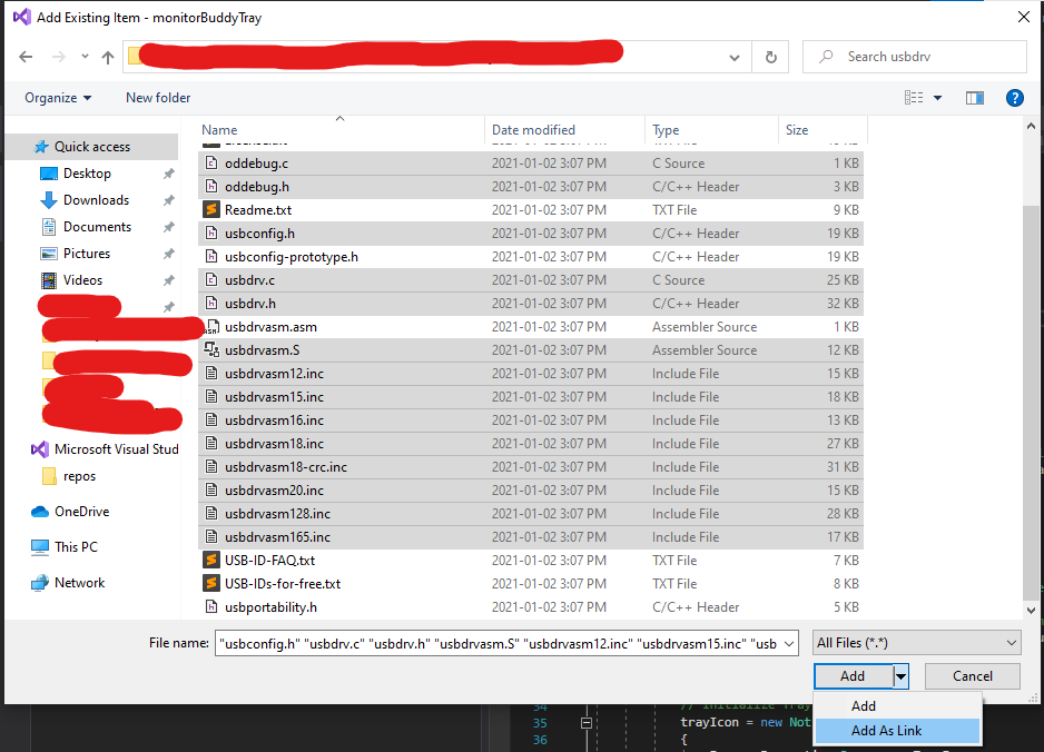
Create a new c# project. Add the libusb-1.0.dll/pdbs from vcpkg/installed as “existing items” to your project. As content they should get copied to the output directory, but they need to be in the root of the project for this to work. Otherwise you’ll have to edit your .csproj file and do something like:
  <ItemGroup Condition="'$(Configuration)'=='Release'">
    <ContentWithTargetPath Include="lib\Release\AudioEndPointLibrary.dll">
      <CopyToOutputDirectory>PreserveNewest</CopyToOutputDirectory>
      <TargetPath>libusb-1.0.dll</TargetPath>
    </ContentWithTargetPath>
    <ContentWithTargetPath Include="lib\Release\libusb-1.0.pdb">
      <CopyToOutputDirectory>PreserveNewest</CopyToOutputDirectory>
      <TargetPath>libusb-1.0.pdb</TargetPath>
    </ContentWithTargetPath>
  </ItemGroup>
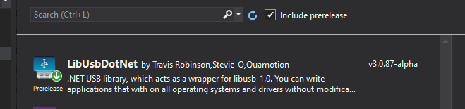
Note the condition on the config – you can make a corresponding one for debug or just remove the condition to use these for both release & debug. Now add libusbdotnet nuget package – as of this writing, make sure you have “include prereleases” checked:
Since I’m also interested in enumerating/setting windows playback devices, AudioEndPointLibrary came in very handy here. It has a c# wrapper dll for .net, just add it as a reference after you’ve built it. Put these all together, and you get something like this, a very dirty proof of concept that allows me to press a button on the breadboard, and change the default playback device in Windows. Now I can move on to prototyping a board for it and formalizing what the software is going to look like.